Week 10, Assignment 10
Output Devices
Goal
This week’s assignment is about adding a output device to a microcontroller board I have designed and program it to do Something.
Introduction
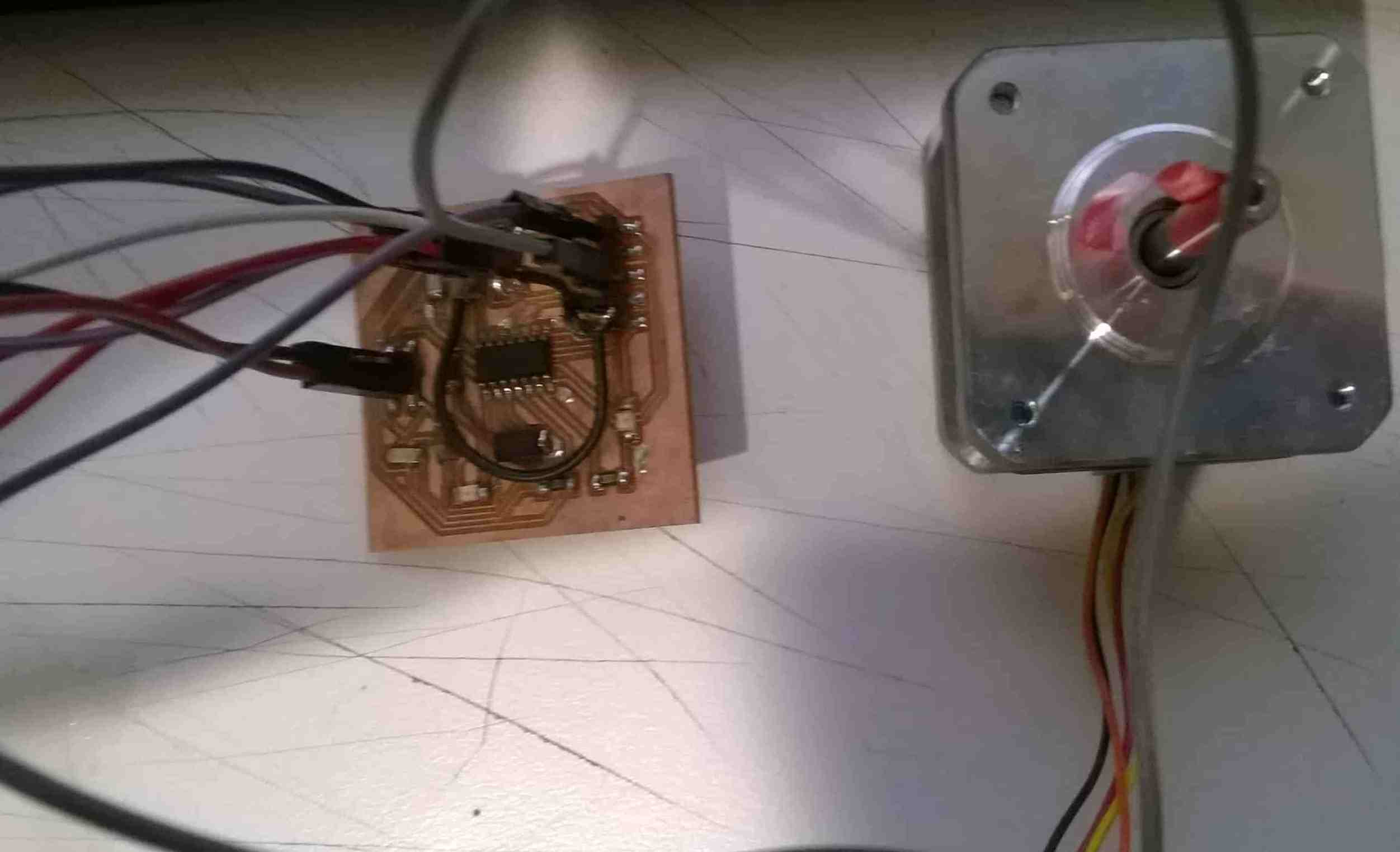
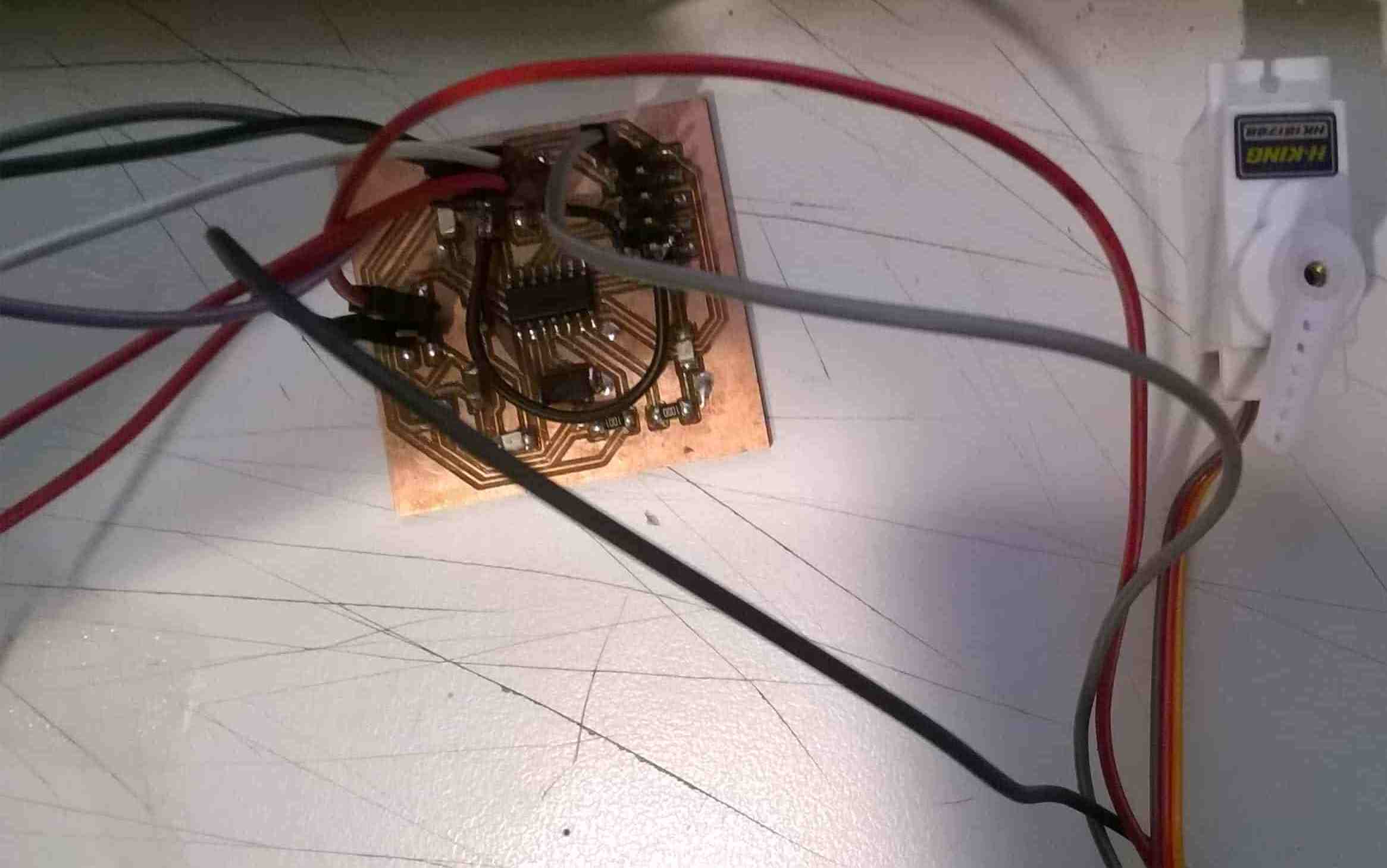
Output Devices like printers, Motors, Screens, Speakers, LEDs, etc are the things which presents the Data. So in this week I decided to make a circuit which will allow me to rotate a Servo Motor and a Stepper Motor.
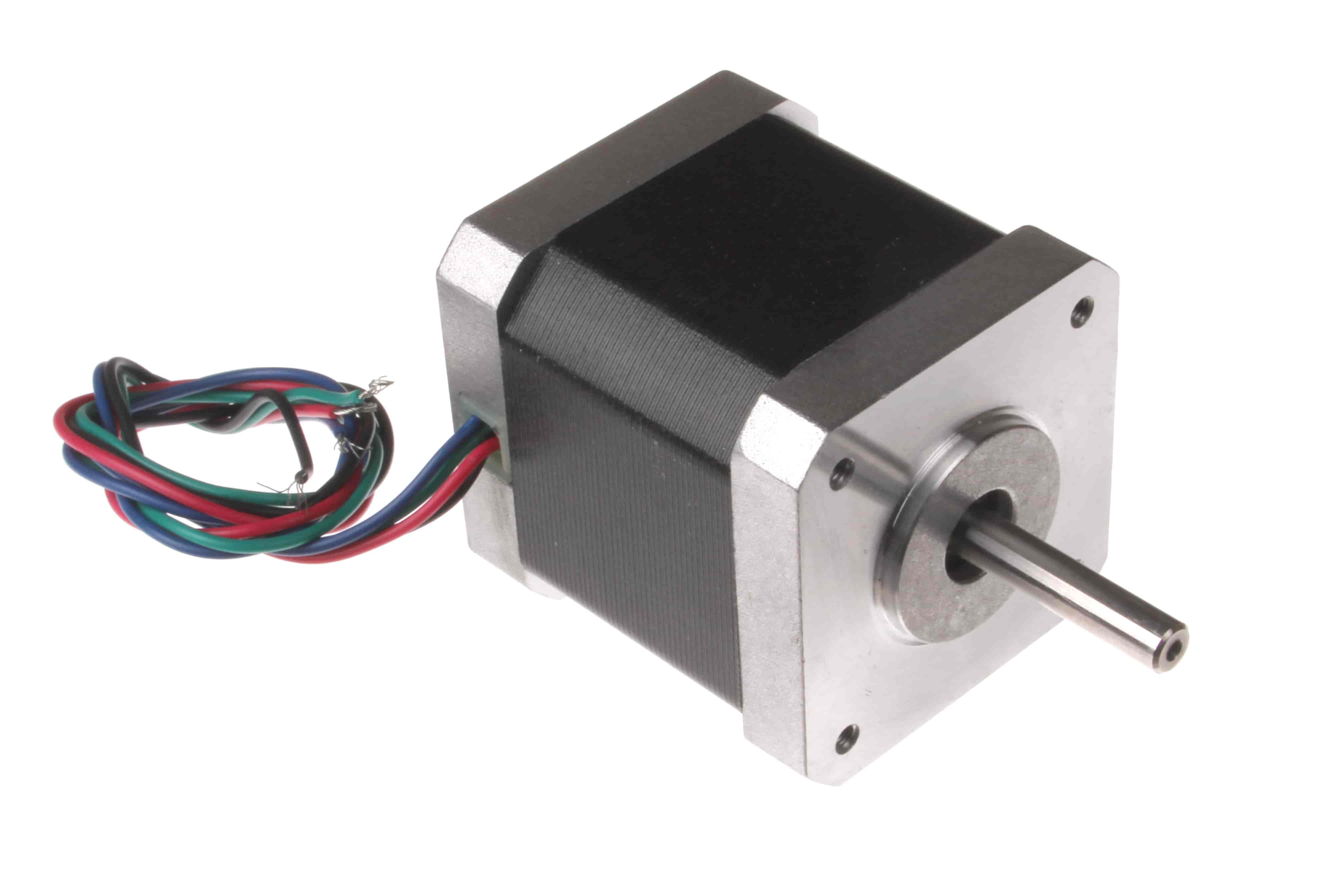
Stepper Motor: A stepper motor is a DC electric motor that drives a full rotation into a number of equal steps. The motor position can then be commanded to move and hold at one of these steps without any feedback, as long as the motor is sized to the application in respect to torque and speed.
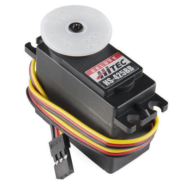
Servo Motor: A servomotor is a rotary or a linear actuator that allows for precise control of angular or linear position, velocity and acceleration. It consists of a suitable motor coupled to a sensor for position feedback. Servomotors are used in applications such as robotics, CNC machine, etc.
Designing:
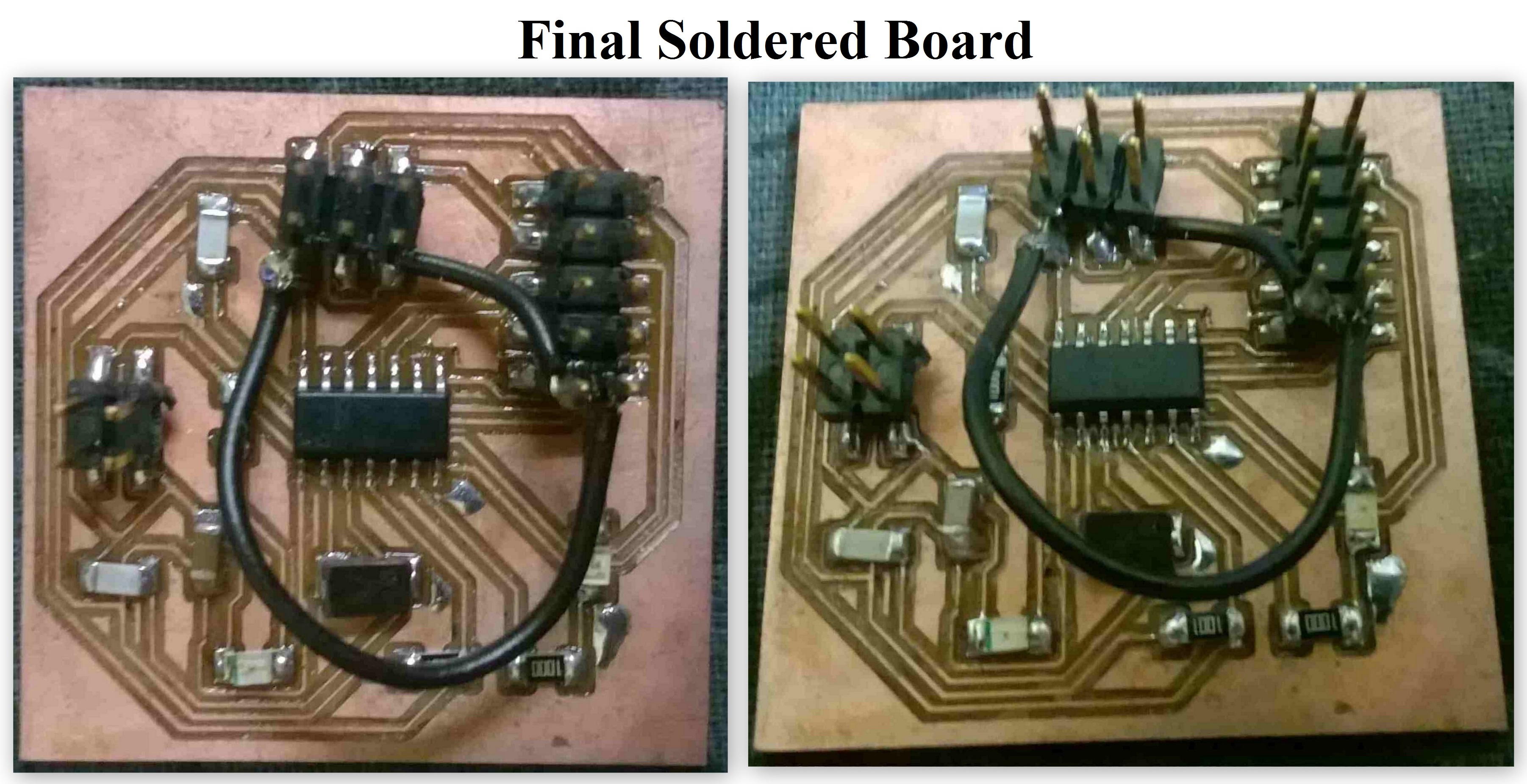
For Designing the circuit I used Eagle software as I used it before also for making the circuit diagram using Schematic and Board files. There were different board files available in the Output Devices page which Prof. Neil told us about, but then I decided to make a different circuit so that I can use that same circuit board for multiple applications. So I then decided to edit my helloworld board file which I made in my Electronics Design assignment. In that I just removed the button and added Pins for connecting anything which can be used with that Pins. I then also added two more VCC and GND pins extra if in case needed. I had tough time making the board file then, tried several times but was getting proper tracks for final milling of the board, but finally as I got tired and was just left with only two unrouted tracks in the board file, I took it for milling and decided to join the two open tracks with the help of jumpers. Finally then my board file was as shown below;
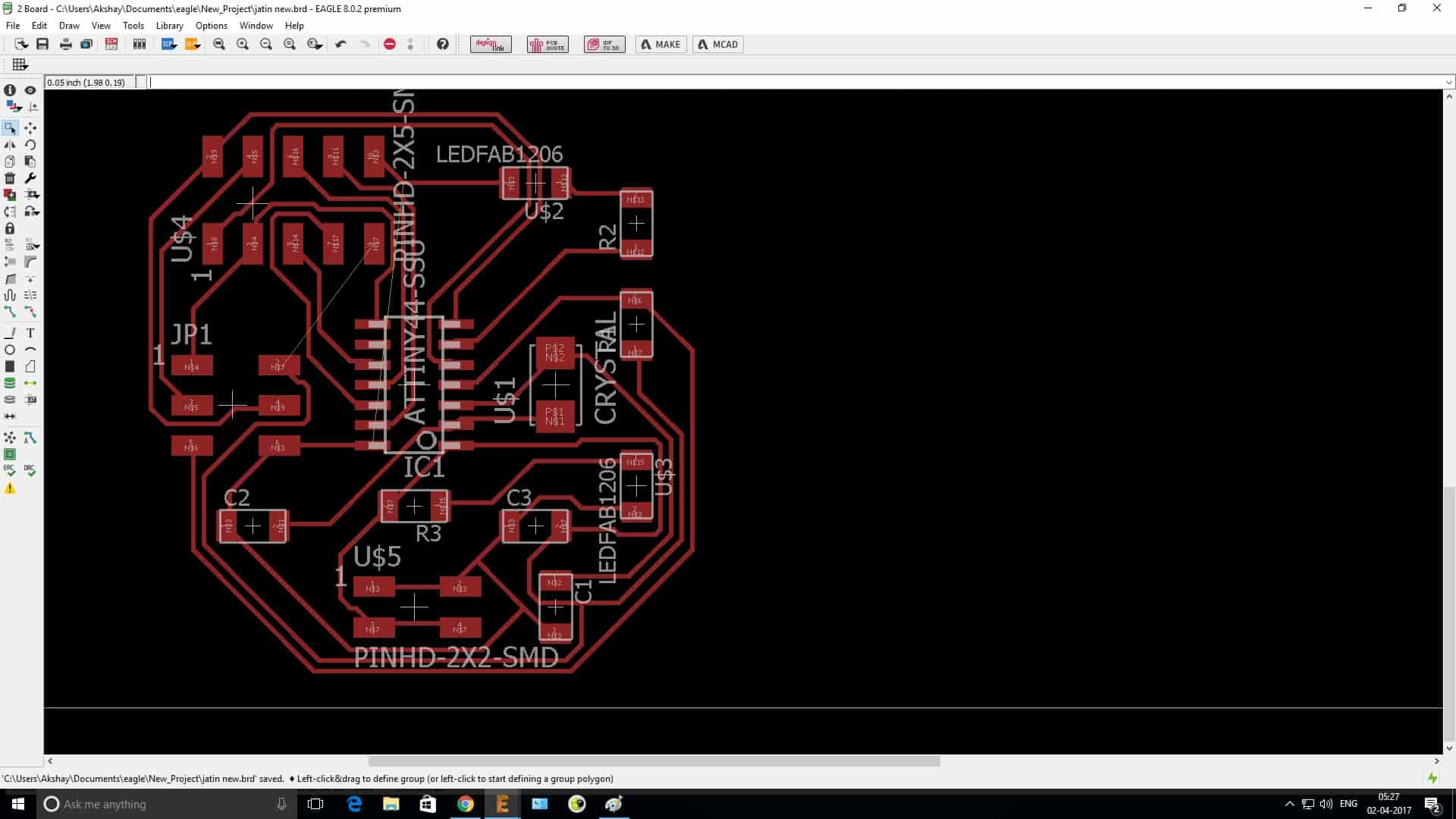
I used Attiny 44 as my microcontroller who's data sheet I had gone through with, so it wasn't tough to do the programming for that. I have mentioned about the Data Sheet study in Electonics Design assignment.
Programming:
For Programming I used Arduino IDE 1.8.1, Code can be seen below;
Program for Servo
#include
Servo motor;
int angle = 0;
void setup() {
motor.attach(8);
}
void loop() {
for (angle = 0; angle <= 180; angle += 1) {
// in steps of 1 degree
motor.write(angle);
delay(15);
}
for (angle = 180; angle >= 0; angle -= 1) {
motor.write(angle);
delay(15);
}
}
Program for Stepper
#include
const int StepSize = 200;
Stepper STMotor(StepSize, 8, 9, 10, 11);/span>
void setup() {
STMotor.setSpeed(60);
Serial.begin(9600);
}
void loop() {
Serial.println("clockwise");
STMotor.step(StepSize);
delay(500);
Serial.println("counterclockwise");
STMotor.step(-StepSize);
delay(500);
}